About the author:
Stephen Dalton, P.E., is director of engineering for Val-Matic Valve and Mfg. Dalton can be reached at [email protected].
What is a Torque Tube?
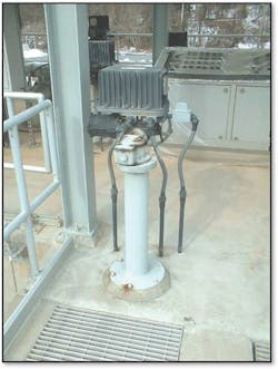
A floorstand assembly is used to elevate an actuator above the valve it operates in cases where the valve is submerged or inaccessible to personnel. A floorstand assembly is bolted to the floor or grating directly above a quarter-turn valve. An inner shaft, or torque tube, transfers operating torque from the actuator to the valve to move the valve between its open and closed positions.
The assembly features a large diameter floorstand to support the actuator and restrain it from turning. Inside the floorstand, the torque tube turns 90 degrees to operate the valve open and closed. The torque tube rests on the valve below and includes adjustable stop bolts to precisely locate the valve’s closure member (disc, plug or ball) in the closed position.
Installation of a torque tube and floorstand must happen after installation of the quarter-turn valve below. A true plumb installation of the actuator, floorstand, torque tube, and valve stem will allow for smooth and reliable valve operation.
How to Install Torque Tube: Step-by-Step
- Make sure the actuator and valve are in the same position. Both the valve and actuator should be in the open position for plug valves. Both the valve and actuator should be in the open position for butterfly or ball valves, as well. For butterfly valves, it is critical the disc be closed evenly within 1/8-in. difference from side to side for 24-in. and smaller valves. Thirty-inches and larger butterfly valves must be closed evenly within 1/4-in. difference from side to side. Measured confirmation of the evenness of the disc also will be necessary to set travel stops later in Step 9.
- Remove the indicator arrow and gear cover from the actuator on the floorstand assembly. Remove the key and set it aside for later reassembly.
- For butterfly valves, ensure the packing retainer plate is in place.
- Check the female (bottom) coupling of the torque tube to see if a key is fastened in place. If there is no key assembled to the bottom torque tube coupling, insert a key into the valve shaft.
- Secure the torque tube with a strap and lower it onto the valve stem or shaft. For valves with mechanically secured packing, such as plug and ball valves, the torque tube will rest on the valve stem or shaft. For butterfly valves, the torque tube will rest on the packing retainer plate.
- Lower the floorstand over the top of the torque tube. Use a level to ensure the torque tube is plumb and brace it in place. Shim the bottom of the floorstand so the torque tube is centered within the floorstand and ensure there is no binding on the torque tube. Secure the floorstand to the floor with 5/8-in. bolts.
- Insert the key from Step 2 to secure the top of the torque tube to the actuator. Install the indicator arrow.
- For ball and butterfly valves, back out the stop bolts on the torque tube plate as far as possible without removing the bolts.
- Operate the actuator to fully cycle the valve, ending in the closed valve position. For butterfly valves, ensure the disc is even from side to side, as noted in Step 1. This may require adjusting the closed position stop bolt on the actuator to provide additional travel.
- Once the valve is in the closed position, tighten all stop bolts to the torque noted in the table above.
- Once again, cycle the valve from the fully closed position to the fully open position and back to the fully closed position. Ensure the valve operates smoothly without binding and returns to its fully closed position when the stop bolt is contracted.
