Managing Flows for the Fish
The Bull Run watershed has continuously provided water to the Portland, Ore., metropolitan area since 1895. It also plays an important role in supporting the larger aquatic ecosystem of the Sandy and Lower Columbia rivers, where some fish species have been in significant decline.
In response, the Portland Water Bureau (PWB) has developed the Bull Run Water Supply Habitat Conservation Plan (HCP) to make the necessary changes to the city’s drinking water operations in order to help the aquatic environment rebound. Part of the HCP is a water temperature management plan designed to comply with the Clean Water Act, which is a critical component in the rehabilitation of the fish stock.
Problem
The water temperature of the Sandy River during summer months was too warm, making it difficult for the fish to spawn. The river got too warm because the source of the river water is pulled from the top of the reservoir. The PWB consulted with an engineering firm to come up with a plan to regulate the water temperature. A plan was put in place to change the location of the source that feeds the lower river from the warmer top layer to the cooler waters in the lower part of the dam.
To make this happen, they needed a distribution system that would control the amount of cold water entering the system by setting a desired flow rate of cold water. The control system would need to have the capability to measure flow and the capacity to fluctuate from low flows to upwards of 83,000 gpm to make this possible. As the reservoir fill height has an inlet pressure of 45 psi and the water is going into the river at atmospheric pressure, the valve control system had to have the ability to withstand a 45 to 0 psi pressure drop.
Solution
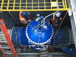
The solution was to use two Singer S106-2SC-PCO-MV-C-AC valves with an MCP-TP control panel. This valve has dual solenoids in the pilot system, which allows the MCP-TP to control the valve and modulate it to the required set points electronically. The valve is equipped with backflow check to ensure that the valve closes in the event of reverse flow. Due to the maximum flow requirements, 24- and 36-in. valves were enough to manage full flow variance. Additional features offered on the valve are the single rolling diaphragm (SRD) and the anti-cavitation option to handle the large pressure drop.
The range between a high flow of 83,000 gpm and low flows would typically require a large valve for the high flows and smaller valves to handle the lower flows, as traditional valves become inefficient at low flows and start to hunt and chatter. But with Singer’s SRD technology, the molded diaphragm provides a constant surface area, no matter the valve position, and avoids injecting small pressure pulses into the piping. By doing this, the valve eliminates seat chatter at low flows, helping to prevent water loss and leakage while providing smooth, precisely controlled flow.
Results
The 24- and 36-in. valves were set to run in parallel, and the controls were consolidated into one panel to save on space and costs. The Singer electronics division designed and built a control panel to receive information from both valves and allow users to control the valves individually. Using a differential transmitter and a valve position indicator from each valve, the MCP panel is able to calculate the individual flows through each valve. This allows the PWB operators to control the valves to specific flow rates by entering a set point into the panel or remotely via SCADA. The panel then sends a signal to the opening or closing solenoid valves to open or close the main valves until they meet the desired flow rates.
“I am pleased to say that we have achieved what we set out to with a fail proof solution that is easy to manage and maintain,” said Andrew Degner, water treatment operations manager for the PWB.
