Low-Pressure Solution
Resource Management Co. (RMC) needed to replace an inadequate, costly and failing wastewater treatment system at the company’s waste recycling center in Plainfield, Ill. RMC needed a system that not only could handle the wastewater flow of 1,050 gal per day (gpd) generated by its 70 employees, but also had the ability to handle additional flow if it decides to expand the facility in the future. The company turned to Carl’s Septic of Lemont, Ill., to find an easy-to-operate and cost-effective system design that would eliminate the costly pumping and hauling of effluent from the employee restroom facility and lunchroom. RMC also was interested in having the ability to monitor the ongoing system operation.
To obtain water usage information as a first step in designing the system, Carl’s Septic installed a water meter. It was suspected that a water leak might be present based on the unusual flow rate, which was uncharacteristic based on the uses of the building. A comprehensive soil test also was performed to determine the best option for the new system based on the knowledge that poor soils in the area had compromised the existing system.
Meeting Regulations
A low-pressure pipe (LPP) system with a daily hydraulic loading rate of 1,050 gpd was selected based on the assumption of the 70 employees working at the facility creating 15 gpd per employee six days a week. This equates to 6,300 gal per week. In order to meet the LPP regulations of Illinois, a reserve area was created for infiltration.
Due to lack of space and inconsistencies in the trench area, a low-profile drainfield system was installed on top of the old drainfield. Geosynthetic aggregate was selected because, if needed, it provides a highly oxygenated area for continuous biochemical oxygen demand reduction. The reserve was calculated to allow the dosage to move away from the system quickly. Effluent is time dosed to an LPP dispersal field with a soil loading rate of 0.27 gal per sq ft per day. The LPP dispersal field size is 5 sq ft per linear ft of EZflow 803H LPP geosynthetic aggregate bundles.
System Advantages
An LPP system is a shallow, pressure-dosed soil absorption system that includes a network of small-diameter perforated pipe placed in narrow trenches. LPP systems originally were developed in North Carolina and Wisconsin as an alternative to conventional soil absorption systems. Often used in areas where a high water table is present, LPP systems also minimize clogging of the soil from localized overloading and anaerobic conditions due to continuous saturation. These systems are ideal for shallow placement, sites with limited land area for an onsite wastewater system, and difficult soils. An LPP system can be installed in a smaller footprint and has the ability to either time or demand dose, providing more uniform distribution, which reduces local overloading of the soil. Dosing and resting cycles also encourage aerobic conditions. Additionally, these systems perform well in shallow placement where the most biologically active zone exists.
System Design
The system includes a 2,400-gal tank with a VBT200 vacuum bubble technology aerator, an A300 Zabel large-flow discharge filter that can handle 6,500 gpd, and a second 2,400-gal dosing tank with a 50-gpd high-head turbine pump and a filtered pump vault controlled by an Aquaworx IPC control panel. The IPC control panel enabled continual system monitoring, and three alarms are trained to the urinals and the toilets. Effluent is retained in the dosing tank for six days, then is dispersed over seven days. The tank feeds an indexing valve that time doses the effluent to alternating sides and is surge dosed down to zero.
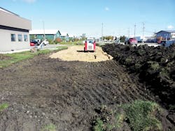
To install the drainfield, a large rectangle was excavated and filled with 6 in. of FA2 and SA2 sand to provide an increased capillary footprint beyond the 2-by-70-ft “real” space needed due to the “disturbed” existing soils. The actual
25-ft-by-150-ft-by-6-in. deep dispersal system sand bed includes 700 ln ft of geosynthetic aggregate bundles placed on top of the sand and split into two 350-ln-ft zones. Each zone receives three 150-gal doses per day with eight hours of rest between pump cycles, which alternate at a rate of five minutes running for every three hours and 55 minutes of rest. There is one LPP pressure adjustment valve per lateral.
The control panel made it possible to identify and repair a leak in the system just after installation, which enabled RMC to reduce overall water usage at the facility. This was critical to the operation of the facility and to gaining final approvals for the system, which has operated per the design since. RMC is pleased with the design and the ease of system monitoring.
Successful Operations
The LPP system designed for RMC is sustainable and yields effective treatment today and for future expansion. It also saved the company considerable operations and maintenance costs and enabled ongoing system monitoring of water usage and system performance.
LPP systems offer the opportunity to effectively treat wastewater on site for new systems and system repairs. Shallow system designs are possible with this approach, expanding the possibilities for difficult sites and those with poor soils or limited space. Challenging sites increasingly are common, with shallow groundwater and varying poor soil conditions being two of the most common obstacles that system engineers and designers must work around.
With technology such as geosynthetic aggregate and remote monitoring and control now available, these systems are becoming popular with installers, engineers and regulators.
Download: Here
