About the author: Erin Boudreaux is marketing manager for Hobas Pipe USA. Boudreaux can be reached at [email protected].
Denver and Aurora are the principal cities of the Denver metropolitan area in Colorado. Aurora, with a growing population of more than 300,000 residents, is home to a vibrant business environment that includes major industries such as aerospace, military, renewable energy, high-tech, biotechnology and health care, and distribution and manufacturing.
The majority of the wastewater generated in Aurora is conveyed through the Tollgate Creek Interceptor to the Metro Wastewater Reclamation District’s Robert W. Hite Wastewater Treatment Facility. The interceptor begins in the southern portion of the city and runs north along the banks of the Tollgate Creek to the treatment plant.
Planning Ahead
Installed in the 1980s, the Tollgate Creek Interceptor consists of reinforced concrete pipe and varies in diameter from 30 to 42 in. Based on future planning, the city of Aurora identified the need for additional capacity in the Tollgate system. Another consideration was the poor condition of the existing interceptor. Pipe samples from the existing Tollgate Interceptor line indicated significant deterioration.
In order to handle future flow, the city embarked on a multi-year capital improvement program to design and construct a new interceptor parallel to the existing Tollgate Creek Interceptor. The new system was designed to divert all sanitary flow into the new interceptor, which would allow the existing interceptor to be inspected and rehabilitated before both would need to be in service.
“The city requested that the new interceptor be designed to transport all flow for 10 years after completion of construction,” said Swirvine Nyirenda, P.E., senior project manager for Aurora Water.
The project was divided into two separate projects, Tollgate Creek Interceptor North and Tollgate Creek Interceptor South. Tollgate Creek Interceptor South was completed in January 2011 and was installed by direct bury and trenchless methods.
Construction on Tollgate Creek Interceptor North began in December 2010 and was installed by BT Construction Inc. of Henderson, Colo. Ten thousand feet of 42-in. centrifugally cast, fiberglass reinforced, polymer mortar (CCFRPM) pipe was supplied by Hobas Pipe USA. Pipe materials allowed on the project were fiberglass-reinforced plastic, high-density polyethylene and polymer concrete. BT Construction bid the project using CCFRPM.
“We were comfortable with the product, as we had used Hobas before and had a good relationship with the company,” said Brenden Tippets, project manager for BT Construction.
Going Trenchless
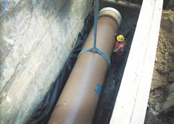
Trenchless methods were used for 4,500 ft of the project because of its urban location. The project area included creek and road crossings, transportation projects and existing utilities. Five thousand, five hundred feet were direct buried in the open areas that allowed access. The pipe was designed and manufactured with a stiffness class of 46 and 72 psi.
“Because the alignment of the pipeline followed Tollgate Creek and had major road crossings, it was decided early in the design process to incorporate trenchless installation methods. The thought was that trenchless installations would minimize the risk to public safety, private property and the environment. In the end, microtunneling with a tunnel-boring machine combined with the appropriate ground modifications where necessary and direct bury were all considered as acceptable pipe installation methods. Each of these was coupled with allowable pipeline materials,” Swirvine said. Because of the close proximity to Tollgate Creek, microtunneling was less likely to cause embankment failures.
Installation Obstacles
The pipe was installed within runs between manholes, with 21 manholes located along the interceptor. “The installation method depended on soil conditions between manholes,” Tippets said. The drives averaged between 500 and 700 ft. Some portions of the interceptor exceeded 35 ft in depth.
The trenchless sections were designed as a two-pass system with the Hobas carrier pipe installed in 54-in. steel casing. The steel pipe was jacked in behind a tunnel-boring machine and then the carrier pipe was installed in the tunnel. In the next step, the annular space between the liner and carrier pipe was grouted. Corrosion resistance was important because the line was gravity flow and had to be resistant to acid attack. Because the pipe was joined in the tunnel, it was manufactured with FWC couplings attached to one end. The FWC coupling is a structural filament-wound sleeve overwrapped and mechanically locked to an internal full-face elastomeric membrane.
There were many challenges associated with this project. It was a deep pipeline and very wet, with a high table of groundwater.
“We were working in small easements and in areas less than 20 ft wide, laying pipe in wet conditions and at depths greater than 20 ft. Soil conditions varied on every tunnel segment, which created a lot of thinking on our feet to adjust to the new condition,” Tippets said. In addition, many utility conflicts had to be resolved over months of planning. “We addressed these challenges by being able to adjust on the fly with our diversity in construction and different installation methods.”
Download: Here
