Colombian Hydroelectric Plant Solves Flooding Problems
The Colombian State of Antioquia creates much of its clean power from hydroelectric plants along the Guadalupe River. In the case of the Guadalupe IV hydroelectric plant, the risk of flooding required that a suitable solution be provided to ensure that the ejector pumps would work regardless of power or pressure differentials.
The Problem
The plant generates power with three vertical-axis turbines that discharge water below the river level. The lower part of the plant is susceptible to water leakage and is designed to continue operating with a certain amount of flooding. The river runs beside the roundhouse that discharges water from the three turbine units.
The leakage of the filtered water from the turbines, hydraulic valves, regulators, water snails, penstocks and draft tubes cones is collected in a well. Three vertical pumps have been installed inside the draw-well—two pumps with a suction capacity of 100 L per second (1,585 gpm) and a flooding pump with a capacity of 200 L per second (3,170 gpm). The pumped water travels through two 30-in. pipes that discharge into the river.
Level sensors are installed on the drainpipe, so when the level in the sump reaches 330 cm above the bottom slab, a signal is generated to indicate potential flood risk. This, in turn, signals a butterfly valve installed on the valve chamber to partially shut down the plant. This means the plant is not able to generate the power that it should until the problem is rectified.
The Solution
With several flooding events in the past, the Guadalupe IV hydroelectric plant designed a group of ejectors that do not depend on the electrical systems and serve as a reliable backup should flooding occur. With this system in place the power plant can continue to produce uninterrupted power to its customers.
The ejectors receive water through a 6-in. pipe with three legs installed upstream of the generator’s inlet valves. The inlet pressure generated is 40 bar (580 psi) (static pressure) with a total flow of approximately 235 L per second (3,724.75 gpm). The problem is the ejectors are designed for a specific flow and pressure conditions, so any changes on those variable values will affect the performance significantly. The optimum operating conditions for those ejectors is 80 L per second (1,268 gpm) at 27 bar (392 psi).
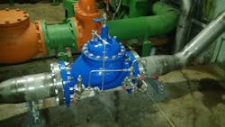
To ensure these variable conditions remain constant, the engineering team looked at installing automatic control valves. The original project was designed with a plunger valve, but this was not a good option, as the pressure drop across the valve would cause cavitation, which can be loud, cause vibration, choke the flow and create erosion that results in equipment failure and surging that can lead to pipe bursts. After further evaluation, they chose to go with Singer’s 8-in. pressure-reducing control valve with anti-cavitation trim.
This valve comes with a single rolling diaphragm (SRD) technology that provides smooth, steady and precise pressure control from maximum to virtually zero flow. The effective area of an SRD remains constant so the bonnet is much smaller and lighter than a flat diaphragm version. A measured quantity into the bonnet control chamber always gives the same smooth movement of the inner valve through the entire stroke. A smaller bonnet also makes the valve lighter and safer for maintenance, while the smaller control chamber enables it to respond faster to changing pressures. By eliminating the seat chatter at low flows, the SRD avoids injecting small pressure pulses into the piping, which, over time, may increase leakage, losses or pipe bursts.
The anti-cavitation cages have been designed for a flow of 80 L per second (1,268 gpm) and can reduce the pressure up to 27 bar (392 psi), thus allowing the ejectors to operate at optimum conditions. This anti-cavitation technology contains two heavy stainless steel sliding cages that maximize the full flow capacity. The first cage directs and contains the cavitation recovery, allowing it to dissipate harmlessly; the second cage allows further control to a level as low as atmospheric pressure downstream.
[Visit Singer Valve's W&WD Storefront]
“By installing this pressure-reducing control valve with anti-cavitation instead of the original plunger valve, we reduced the cost of the operation from 130 million Colombian pesos ($70,000) to 18 million Colombian pesos ($9,800),” said Engineer Santiago Ramirez, spokesperson for the hydroelectric plant.
