About the author:
Steven London is president of Steven London Associates. London can be reached at [email protected].
Designed to reduce environmental impacts resulting from combined sewer overflows (CSOs) in Columbus, Ohio, the Olentangy Scioto Interceptor Sewer Augmentation Relief Sewer (OARS) is a sewer tunnel that will intercept wet weather overflows that currently empty into the Scioto River and instead carry them to the city’s Jackson Pike and Southerly wastewater treatment plants (WWTPs).
The tunnel will provide relief to the existing Olentangy Scioto Interceptor trunk sewer (OSIS) from just north of the Arena District of the city to the Jackson Pike facility. Construction of phase one began in September 2010 and involved three shafts. Shaft 1 is a 20-ft-diameter tunnel with a total length of 23,300 ft for the pump station minus the equipment; shaft two is for the screen structure; and shaft six is the northern terminus. Phase two began in August 2011 and involves construction of three intermediate drop shafts (shafts three, four, and five), a pump station, a pump electrical building, a river overflow structure and other infrastructure.
The overall length of the OARS tunnel is just less than 4.5 miles, and it will include three relief structures that will divert wet weather combined sewer flow from the OSIS to the OARS tunnel. The OARS tunnel is sized to provide adequate conveyance capacity through 2047 for all storms within a typical year as defined by the city. It ends at the OARS Diversion Structure (ODS shaft one) just north of the Jackson Pike wastewater treatment plant, which serves as the pump station wet well.
The tunnel also will provide about 60 million gal of inline storage during critical periods to reduce or eliminate CSOs. Per the city’s consent order with the Ohio EPA, discharges from 12 CSOs along OSIS will be eliminated for up to a 10-year flow event; the Whittier Street storm tank overflows will be eliminated during the “typical year”; and the overflows at the Jackson Pike WWTP will be limited to no more than four during the “typical year.” This will result in the elimination of nearly 2 billion gal of CSO each year.
Deep, Deep Tunnel
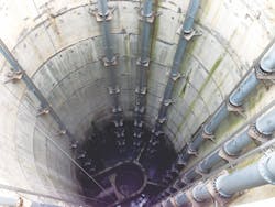
The tunnel is being built approximately 170 ft below ground, reducing risks associated with construction at shallower levels. This will require special drop structures (or vertical shafts) to direct flow from existing shallow sewers to the new deep tunnel. In addition, the drop structures will dissipate energy and minimize air entry into the tunnel. The tunnel shafts are designed to handle hydraulic surges, which will prevent impacts on upstream sewers.
Among the most interesting components of the OARS project is a 215-ft-deep, 60-million-gal-per-day (mgd) pumping system and a 185-ft-deep screening system. The OARS pumping system consists of multiple pumps that can handle enough flow to dewater the tunnel within two days of a large flow event. The difficulty with the deep pumping system for this project is that the static head condition varies from as much as 210 ft when the tunnel is empty to as little as 15 ft when the tunnel and shafts are full.
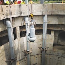
The solution consists of four Flygt Model CP3351.995 800-hp, 4,160-VDC, 15-mgd adjustable speed pumps that handle the majority of the work at the deep tunnel level, and two Flygt Model CP3531.960 450-hp, 4,160-VDC, 20-mgd adjustable-speed pumps to handle the shaft dewatering. Two grit pumps, a Flygt Model NP3301.095 105-hp, 460-VDC and one Flygt Model NP3306.715 100-hp, 460-VDC pump also were installed. Pump selection was critical to achieve high efficiency and to minimize operational issues and power consumption. The pump manufacturer also provided the variable frequency drives for eight pumps and an MAS monitoring cabinet for all nine pumps as well as all guide rails and associated brackets.
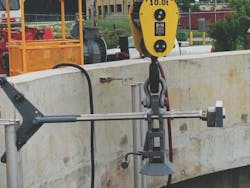
Physical modeling was utilized to determine the depth of the wet well and the baffling configuration to eliminate the risk of vortex formation causing air entrainment, and to determine cutoff elevations for the large pumps to minimize the possibility of air entrainment. Two separate grit chambers are provided to catch any heavy solids that get washed down the tunnel into the wet well. A wet well mixing system also is provided to assist maintenance and cleaning of the wet well. A bridge crane is provided for pump retrieval and installation. A clamshell bucket also can be utilized to remove any debris accumulating in the wet well.
A Circular Model Wet Well
The wet well was designed around a circular model. Ideally, the flow of fluid into any pump should be uniform, steady, and free from swirl and entrained air. Lack of uniformity can cause a pump to operate at a lower efficiency rate. Unsteady flow causes the load on the impeller to fluctuate, which can lead to noise, vibration and bearing problems.
Swirl in the pump intake can cause a significant change in the operating conditions for a pump and can produce changes in the flow capacity, power requirements, and efficiency. It also can cause local vortex-type pressure reductions that induce air cores extending into the pump. This, and any other air ingestion, can cause reductions in pump flow and fluctuations of impeller load, which result in noise and vibration with consequent physical damage. Additionally, these fluctuations can impact process loads in other parts of the system.
Circular wet wells can be deep with have large capacities and limited footprints; these are common demands by customers for their pump stations designs. From an investment and operational perspective, installing submersible pumps in a circular wet well design is a suitable solution in cases such as these. Flygt pioneered the installation of submersible pumps in large-capacity circular wet wells and has gained significant experience in this area from model testing and proven installations.
The phase one contractor used slurry panels to provide a watertight support of the excavation system in the top 115 ft soft-ground portion of the shaft. The lower 100 ft of excavation was in rock. It first was pre-grouted, and then drilling and blasting excavated the bottom of the shaft. A finishing wall of concrete that was 2 ft thick in the rock section and 3 ft thick in the soil section was installed to create a permanent watertight wet well shaft. The 50-ft-tall baffle wall system was constructed within the shaft. Upper flow diversion channels were built around the top portion of the shaft. The structural top of the shaft was finished with a 113-ft-by-83-ft concrete pad with a 42-in. parapet wall around the opening of the deep shaft.
The phase two contractor then took over the shaft and installed all the piping and supports. Installing the piping support system required everything to be lined up perfectly to allow for 10-ft-tall pump installation and retrieval along straight guide rails over the 215-ft depth. A great deal of coordination was required on the shop drawings to ensure adequate space for everything to fit just right. The contractor installed bracket supports with a SkyClimber system (window washing suspended access equipment) hanging down from the parapet wall.
This project—the largest capital improvement project ever undertaken by the city of Columbus, Ohio—was realized at a total construction cost of just under $371 million, of which the pumping system alone cost about $13 million. Financing for the project was handled through low-interest loan funds available from the Ohio EPA, and the debt will be serviced through revenue from Columbus sewer customers.
Wet testing of the pumping systems was completed in April 2017, and the system has been handling live flows since early July. Faced with a huge CSO problem, Columbus has combined sound engineering with state-of-the-art equipment in the OARS to deliver the solution to CSO issues for decades to come.


