A good pumping system does not make it to the local news. A successful pump station incorporates all aspects of its life cycle — from design and contract execution to installation, operation and maintenance. This article explores the hydraulics side of these aspects for a successful pump station.
Design
A thorough understanding of the pump station’s type and intent is foundational to a successful station, best achieved by understanding the end user’s expectations of how they will operate it. Wastewater pump stations within collection systems are designed to remove influent sewage and deliver into a force main and eventually to a treatment plant. Activated sludge pump stations, thickener feed pumps or other process pump systems are typically flow-paced.
Several codes and standards are available for pump station design, with the Hydraulic Institute (HI) providing standards and guidelines that are most notable and comprehensive.
Design begins with understanding the range of flows that a system needs. At a lift station, for example, the diurnal influent flow curve on an average day provides the range of flows for normal operation. If high influent and infiltration is expected in the collection system during a storm event, peak day influent is assessed. If a wide gap is observed between normal daily and seasonal peak wet weather flows, then the flows can be handled separately by a set of dry and wet weather pumps. If the gap is narrower, appropriate pump sizing with multiple pumps to handle the range is the key. System head curves are developed early in the design to understand the pumps’ operation at various influent conditions. Pump selection should be based on operating the pumps within their preferred operating range and maximizing energy efficiency.
Wet well design is also important in providing clean influent hydraulic conditions to a pump. Following HI guidelines is the first step in design while following best industry practices. For example, a sewage lift station wet well’s design should minimize footprint but also provide adequate storage to minimize pump cycling. A good wet well design incorporates details of clean-out cycles to minimize solids accumulation. Sloped floors towards the pumps, avoiding dead spots in the wet well, and appropriate pump type for the solids handled are very important considerations. Design of wet-pit vs dry-pit pumps is a common question.
A Nevada utility experienced significant clogging issues in its sewage pump station due to flushable wipes. A new pump station is being designed with chopper pumps. The utility wanted to try a pump ahead of time and installed one in 2022. After about 4,000 hours of operation, the pump did not require any down time compared to a non-clog pump, which required clean-out every week.
Several effluent quality water pump types are available to deliver the same flow and head at the duty point. But if the system curves are steep, careful considerations should be given to the pump type, knowing that may dictate the runout condition operation.
When dynamic losses are a significant portion of the total head, a vertical turbine pump — with a typically steep curve — may be a better fit.
Specifications of the pumping units should get careful attention. The HI does not have stipulated vibration magnitudes for motor vibration on a vertical pump, for which appropriate limits should be specified for maximum allowable motor vibration. For applications involving tall units, separation margins between critical and operating speeds should be specified exceeding the industry standard and enforced during shop drawing reviews.
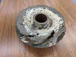
Material specification for pumping units needs careful review. For pumping units in reuse systems with high residual chlorine, it is recommended to specify impellers with less than 0.5% zinc. Dezincification of impellers with high zinc content is a phenomenon that can reduce the impeller life to just months (see Figure 1). Aluminum bronze (ASTM B148) or stainless steel impellers are recommended for most clean water applications.Transients
Transient analysis may be required for systems involving complex operations (e.g., quick opening/closing of valves, several high points, significant static heads). A thorough transient analysis is required for properly sizing air valves and other transient mitigation methods. Slow ramp up and shutdown of pumps is recommended for pumping units larger than 50 horsepower.
A Kansas City utility had several minor pipe breaks resulting in sewage overflows into adjacent farmlands on an 8-inch ductile iron (DIP) force main within 10 years of installation. Fatigue loading of the pipe to positive and negative pressures and sustained negative pressures for several seconds within the force main may have caused damage to the pipe’s internal lining. After transient analysis, reduced voltage soft starters (RVSS) were installed on the 50-horsepower submersible pumping units with ramp rates of 15 seconds. No additional pipe breaks happened over the past four years since installing the RVSS.
Installation
Proper installation of a pumping unit is critical, starting with the design of a good foundation for the pumping unit, which must be substantial enough to absorb vibratory loads.
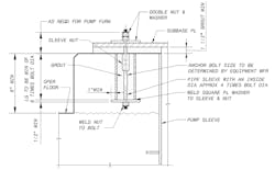
For vertical pump units, anchorage relies purely on the clamping force of a pre-tensioned anchor bolt to the grouted baseplate. For vertical pumping units larger than 100 horsepower, it is highly recommended not to use post-install anchors. Install the anchor bolts in a sleeve that allows for pretension (see Figure 2).
Baseplates for horizontal pumping units are only designed to transfer the loading to the foundation, so grout holes should be provided to fill the baseplate with non-shrink grout.
The equipment base should be grouted before final bolting of connecting piping. Appropriate joints with HI-compliant harness rods should be installed. Pump discharge and suction nozzles cannot accept excessive loading, and special care should be taken with the alignment between pump nozzles and connecting piping.
In Missouri, a utility experienced significant damage to high horsepower distribution system pumping units. The first time the pump was turned on — as recalled by an operator — the pump “walked away from the pipe.”
An investigation concluded that inadequate harnessing of the pump discharge connection caused excessive nozzle loading. A properly designed thrust restraint on the pump discharge ultimately was installed to alleviate that issue.
Controls and operations
Operating pumps and the pump station within design parameters extends the station’s life. Appropriate suction levels or pressures are required to prevent damaging cavitation conditions. Adequate protective controls enable precautionary alarms and shutdowns during adverse operations.
For example, switches should be provided for pumps 100 horsepower and larger to protect against high vibration, high motor temperatures, low suction pressures and high discharge pressures outside of design parameters. If operating a pump outside the design parameters is required, careful consideration should be given to the limits at which the pump is tested in its factory.
Maintenance
It is usually up to the end user to appropriately maintain the pumping system. Most times, inadequate attention to periodic maintenance results in disrepair and could result in catastrophic failures.
Periodic clean-out cycles of the wet well for sewage systems (at least once a week) is necessary to bring the wet well level lower than the normal operating levels. Force mains with low points should be cleaned out periodically with high-velocity water. Cleaning and pigging of force mains with extended low points (e.g., river crossings) are recommended every several years.
Critical pieces of a pumping system include air valves, which, when not maintained properly, can become plugged with fats, oils and greases that often build up in sewage force mains. Cleaning those valves should include air valve body, internal components, and the riser pipes between the air valves and the force main.
Conclusion
Appropriate design, proper pump selection and sizing, operating the system within the design parameters and taking adequate care of the equipment will deliver a system that outlasts and outperforms expectations of the engineer, the manufacturer and the end user.
About the Author
Raghu Kadava
Raghu Kadava is a Black & Veatch expert on pumps and hydraulics. As a contributing member of the Hydraulic Institute technical standards committees, he has experience in design, installation, testing, hydraulic transient analysis, startup and commissioning of hundreds of pump station projects. He also is a certified Pump Systems Assessment Professional (P.S.A.P) by the Hydraulic Institute.


