About the author:
Branden Powell is Supervisor of Environmental Process for City Water Light and Power (CWLP) in Springfield, Illinois. Powell can be reached at [email protected] or 217.757.8670 ext. 2487.
In 2016, as City Water Light and Power (CWLP) was preparing for the latest rulings to the Effluent Limit Guidelines (ELG) addressing tighter limits on discharges concerning flue gas desulfurization (FGD) wastewater, a water balance was conducted on all four coal-fired electric generating units to see just how much FGD wastewater was being produced that would require treatment. The goals of this water balance was to find areas of optimization, reduction and reuse. The first step, and arguably the most important step to any wastewater treatment program, is to reduce the amount of wastewater that will require treatment where possible.
It was during this water balance that the hydroclone system used to dewater the gypsum product slurry produced during the FGD process on one of the larger generating units — Unit 3 — was not operating as efficiently as originally designed. This means excess FGD wastewater was being produced. Further performance testing on this hydroclone system confirmed the water balance findings. From these results, a new hydroclone system was chosen that not only performed more efficiently but offered better performance monitoring capabilities. Once startup and commissioning of the new system was complete, a determination in FGD wastewater reduction could be explored.
Background
CWLP provides electricity to the city of Springfield, Illinois, from four coal-fired units complete with wet FGD systems to remove sulfur dioxide (SO2) from the boiler (flue) gas produced during coal combustion. Limestone reagent slurry with greater than 95% calcium carbonate reacts with the SO2 entering the FGD system with the flue gas. A synthetic grade of gypsum (CaSO4) slurry is produced under forced oxidation. This gypsum slurry must be dewatered by the use of disposal hydroclones and vacuum drums. The dried gypsum cake is then discharged for resale. The liquid portion produced from the dewatering becomes the FGD wastewater. The FGD wastewater produced from all four generating units is discharged to a phys/chem facility on site to undergo chemical clarification. The clarified FGD Wastewater is then discharged to a publicly owned treatment works (POTW). It is this clarified FGD wastewater that is then the subject of the latest ELG rulings.
Unit 3 has a double loop FGD design consisting of two absorber vessels, north and south, and an absorber feed tank (AFT). Flue gas containing SO2 enters both absorber vessels simultaneously and limestone reagent is added to both vessels from the AFT. However, rarely is gypsum slurry pulled from both absorber vessels simultaneously. The old disposal hydroclone system consisted of eight Linatex hydroclones; four in a bank per absorber vessel with three hydroclones in service and one for spare. This older system was completely enclosed with no sampling or monitoring capabilities, and sample ports had to be installed prior to performance testing.
A hydroclone is described as having no moving parts with the exception of the feed pump. The hydroclone contains two discharge streams: overflow and underflow. The overflow contains a suspension that is more dilute and less dense than the feed, and the underflow contains a suspension that has a greater density than the feed. The hydroclone’s inner system consists of a vortex finder and an apex. The feed slurry is introduced to the hydroclone manifold bank by the feed pump. The pressure from the feed pump causes the feed slurry to spin in the cylindrical section around the vortex finder. The denser product is forced to the outside of the cyclonic mass, which displaces the less dense product and water towards the center. The inner portion is “cut” by the vortex finder and discharged out of the overflow by the internal pressure.
The remaining denser product spirals downward and discharges out of the apex. Thus, excess water is essentially squeezed out and rises in the vortex finder. The overflow discharge is returned to the corresponding absorber vessel for further reaction. The underflow discharge enters a wet well tank for further dewatering by vacuum drums.
Analytical testing of density, percent solids and PSD by laser diffraction on samples from the feed pump, overflows and underflows were conducted to determine the new equipment's performance level.
Performance Testing of the Old Hydroclone System
Analytical testing of the old hydroclone’s performance began in August 2016. Analytical testing consisted of density, percent solids and particle size distribution (PSD) by sieve pan. PSD by laser diffraction was later used in the design and performance testing of the new hydroclone system.
Testing was performed on samples collected from the feed pump, overflow and underflow of the various hydroclones in service. During sample collection, several hydroclones were found to be plugged solid and had to be removed from service for repairs. Results of the performance testing confirmed the majority of the hydroclone overflows were not returning to the absorber vessels, but were instead falling through the underflows. Thus, excess FGD wastewater was passing through the dewatering process.
The testing results were no surprise to FGD operations. For years when operations would pull for absorber level and gypsum production, the level in the wet well would increase dramatically, while the level in the absorber vessels would not decrease much. This resulted in pulling absorber level more frequently and for longer durations of time per eight-hour shift. This indicates excess FGD wastewater discharging to the phys/chem facility more frequently over a 24 hour period.
Designing a Custom Tailored Hydroclone System
After reviewing the performance testing results, it was determined the old hydroclone system needed to be updated with a new system. In September 2016, representatives of Combustion Kinetics Corp. (CKC) and FLSmidth/Krebs were contacted for designing a new system.
The major concern was Unit 3’s dual loop FGD design and determining if a single hydroclone system would be sufficient. Over the course of 2017, CKC and FLSmidth designed a new disposal hydroclone system to suit facility needs.
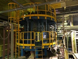
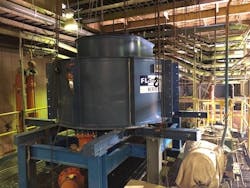
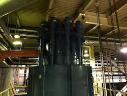
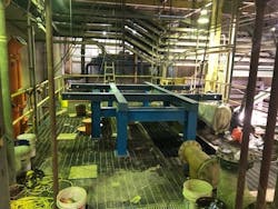
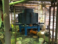
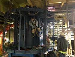
The new FLSmidth hydroclone manifold consists of two hydroclone banks, one for each absorber vessel. Each bank consists of five FLSmidth gMax 6 hydroclones containing a 1.75-inch ceramic vortex finder and a 1.5-inch rubber apex. Each hydroclone bank has an independent overflow launder, but they share a common underflow launder. There are access catwalks with ladders to access both launders.
Both hydroclone discharges are open and accessible for sampling and performance monitoring. The new hydroclone system was installed during the spring maintenance outage for Unit 3 in 2019.
Effluent limit guidelines regarding flue gas desulfurization wastewater required City Water Light & Power to optimize FGD wastewater treatment.
Startup & Commissioning
Once Unit 3 returned to service in May 2019, startup and commissioning of the new hydroclone system began. This included analytical performance testing of density, percent solids and PSD by laser diffraction on samples collected from the feed pump, overflows, and underflows. The result of this testing was to determine the design specifications for these parameters were being met along with overall improved efficiency in performance and operation. Representatives from CKC demonstrated continuous support during this startup time period. Performance monitoring continued over the summer of 2019. After determining that operation of three hydroclones in service and two for spare best achieved design specifications — barring some minor FGD upsets — the new hydroclone system was placed into official service by July 2019 with the rubber apex replaced with ceramic.
Significant Reduction in FGD Wastewater
Once startup and commissioning of the new hydroclone system was complete, a comparison was made in the gallons per day (gpd) of clarified FGD wastewater discharged to the POTW for the months of July, August, September and October 2019 with the same months in 2018.
The only change between the two time periods is the new hydroclone system. To the facility operator's surprise, the time period for 2019 saw a reduction of more than half the gpd discharge of 2018. It was understood there would be some reduction since the new system allows FGD operations to pull for absorber level from 15 to 20 times a shift down to only once or twice daily. This significantly reduced the amount of wastewater discharged to the phys/chem facility.
However, to see a dramatic reduction in FGD wastewater discharge plant wide was shocking. Management then compared this 2019 gpd discharge to the previous five years to see if this trend continued. Again, this greater than 50% reduction in gpd continued when compared to the previous five years of plant operation.
Conclusion
As the facility moves closer to meeting the latest ELG rulings for FGD wastewater treatment, this dramatic reduction will potentially save it from significant capital costs in addition to savings on future physical and chemical treatment design and operation headaches. This project proved the very first and most important step to any wastewater treatment program is reducing the amount of wastewater that will require treatment.
