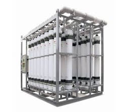
Tips for Successful CIP Procedures
The surface of ultrafiltration (UF) membranes is subject to the build up (fouling) of foreign materials present in feed water, such as suspended solids, colloids, organics and biological matter. The deposits accumulate on the membrane, resulting in decreased filtrate flow and/or increased transmembrane pressure (TMP), eventually reaching levels that cannot be recovered by regular backwash and maintenance cleaning. To reverse this situation, a clean-in-place (CIP) must be performed. A deliberate approach to data collection and analysis before, during and after such cleanings can lead to constant improvements in cleaning efficiency and help ensure reliable system capacity for longer periods.
Indications that UF modules should be cleaned to restore membrane permeability include (specific values are determined by the membrane provider):
- Drastic decrease in permeability;
- Significant increase of normalized TMP; and
- Operating TMP reaches the maximum limit value for the UF product.
CIP is most effective when tailored to the specific cause of fouling. Therefore, analysis into the type of foulants on the UF membrane surface should be done prior to the CIP. There are different ways to accomplish this including:
- Analyze feed water quality looking for specific foulants (ex: metals, natural organic matter, colloids, etc.);
- Review results of previous cleanings to check the most effective chemical solutions used;
- Remove and inspect the feed end of one UF module for indication of contaminants; and
- Inspect, sample and/or analyze the waste discharge after air scour in the backwash step for indication of contaminants.
The permeability (flow/TMP) of the UF membranes to be cleaned should be measured with online instrumentation before and after the CIP with each type of solution to establish a baseline, for assessment of chemical cleaning efficiency and indication of the type of fouling. It is recommended for the permeability (LMH/bar, or gfd/psi) to be measured on normalized terms.
How do you Clean Ultrafiltration Membranes?
The steps for CIP are as follows:
- Install CIP cartridge filter elements (5- or 10-µm rating).
- Make up cleaning solution and preheat to desired temperature. For seawater applications, reverse osmosis (RO) permeate is preferred for the UF CIP make-up solution.
- Conduct a regular backwash with air scour on the UF skid if available. Air scour, a feature that requires vertically oriented modules using outside in flow configurations, is a great tool to loosen particulates deposited on the membrane surface, the removal of which is very important prior to a CIP. Air is introduced from the bottom of the module, on the outside of the fibers and displaced feed flow/concentrate is allowed to discharge through the top for disposal.
- Remove the UF skid from service by normal shutdown procedures and drain out water in the UF skid. Residual water in the skid will dilute the concentration of cleaning solutions.
- Recycle cleaning solution using low-flow pumping. Measure the pH of the solution and adjust the pH, if needed. If the pH increases by more than 1 pH unit during acid cleaning, more acid needs to be added. If the pH decreases by more than 1 pH unit during alkaline cleaning, more caustic needs to be added. Fresh cleaning solution needs to be prepared when the one in place becomes very turbid and/or discolored. This step typically lasts one hour if only one cleaning solution is needed.
- Soak. The soak step is typically two hours. Depending on extent of fouling, an overnight soak of 10 to 15 hours can be beneficial. If an extended soaking period is used, apply a slow recirculation rate (about 10% of the flow used on recirculation step) to maintain a high temperature and to improve cleaning efficiency. Every 30 minutes during the soak period, injection of air for five minutes can be applied to agitate fibers for enhanced cleaning benefits.
- Flush out. After the soak period, drain the CIP tank, and fill with RO permeate (preferred, for seawater applications), potable water, or UF filtrate to prepare for the flush out step. Perform the flush out of the CIP tank and piping by repeating the recirculation step for a period of 10 minutes.
- Conduct a regular backwash, post-CIP, of the UF skid to prepare the system and then return to service.
During the cleaning procedure, chemical concentration, cleaning time, temperature, intermittent air scour and hydraulic conditions are important considerations that will affect cleaning efficiency. Some modules, depending on the material of the fibers, will be more or less resistant to elevated levels of pH, chlorine oxidants and temperature and should be checked for compatibility.
UF system performance should be monitored on a regular and frequent basis. If cleaning is delayed too long, fouling may become irreversible and result in potential physical damage to the UF module or appurtenance equipment. Data should be looked at on a normalized basis, to remove or minimize the effects of temperature, pressure and flow so the user may differentiate between normal phenomena and real performance upsets due to fouling.
Download: Here
