At first glance, the collection of the American gravity sewer looks very uniform.
On flat land, the sewer mains descend to about 16 feet max. At that point, a lift station is constructed, and the sewer is raised to a point a few feet below the surface where it again flows via gravity, ultimately arriving at the treatment plant.
In communities with more terrain, gravity flow may require those same lift stations to overcome significant elevation changes but, ultimately, like on flat land, the sewer arrives at the treatment plant via gravity.
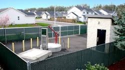
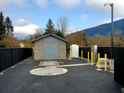
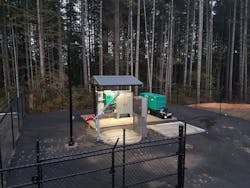
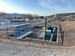
What is different in American sewer collection is the variety of ways the millions of lift stations throughout America are built and configured. Unlike buildings, lift stations do not require review and permitting by something like a building department. For wastewater, each district has essentially developed its own preferences/standards relative to lift station design, configuration, and operation. While they all function in fundamentally similar ways, they are often very different in the way they are built and the way they operate.
The collection and movement of American sewer and wastewater is serious business. Lift stations are expected to always operate regardless of utility power loss or any other single point of failure. In fact, most sewer pumping systems have redundancy in power; pumps; level, start and stop control; and the primary control and communication systems.
What is particularly interesting is the hundreds and hundreds of different ways each sewer district has evolved and refined its particular lift station standards. The following are just some of the variables.
The Sump
In most cases, the inflow line will enter the sump somewhere between 10 feet below grade and 30 feet below grade. In American sewer, designs virtually never allow any lift station to “surcharge” the inlet line, as that could cause a backup and serious consequences.
Instead, the operating area of the sump is located below the invert in. Thus, the area required for the pumps and their operation will typically be anywhere from 5 feet to 15 feet below the lowest invert for incoming wastewater.
Concrete is by far the most popular sump material, and it is often configured and coated to retain its strength and to seal its porous nature. Sumps are often subject to all sorts of traffic loading and potential uplift. They typically house submersible sewer pumps in duplex (two pump) and triplex (three pump) configurations which always provide at least one pump in reserve in the event of a pump failure.
While sumps made of concrete are the most common, there are many proponents of fiberglass sumps as well as a variety of other synthetic sump materials that may be required by one sewer district but never considered by another.
This same variable is also true for the pipes, guide rails, and other assets located within the sump. All these designs and materials are different, and the owner’s preferences for how they are configured is often different. It is important to remember this variance when designing submersible pumping systems.
The Pump
Pumping wastewater requires pumps that can either pass solids or macerate them prior to pumping. The variability of pumps and the various designs associated with pumping wastewater are extensive. In many cases, it is simply practical for a Sewer District to use a single pump brand and, in others, the popularity and/or preference for one brand over another is close to religion.
In most submersible pumping systems, the pumps are started and stopped based on level. Typically, there is a primary level sensing device that starts and stops the pumps. In addition to the primary system, there is also a backup level control system that serves as a pump start/stop failsafe if the primary level control was to fail. Level sensing technology varies from floats to pressure transducers and from radar to conductive probes and bubblers.
They all work, but they all have their strengths and weaknesses. Their respective use is sometimes based on the type of water and/or the volume of that water. More often, their choice is based on what the maintenance people and the operators are familiar with.
In submersible pumping systems, the pumps are at the bottom of the sump. They are connected to the discharge piping which rises in the well and ultimately turns horizontal somewhere between 6 feet and 4 inches below grade. That discharge piping is often stainless steel or a heavy schedule PVC. It often leaves the sump and travels a short distance, 6 feet to 12 feet, where it enters another concrete or fiberglass structure called the valve vault.
Valve Vaults
Valve vaults, and their size and depth, are determined by preference and the size and depth of the assets within them. Their function is to house all the valves and other related mechanical equipment and to allow the operator independent control of each discharge line to open and close, and to prevent back flow.
The valve vault is often where the discharge lines are combined into the one line, which becomes the force main. They also often house a variety of other assets ranging from flow meters to pigging and pumping ports as well as pressure gauges, large hatches, ladders, and drain lines. Like the sump and the pumps, the design options are endless and each district or community has the configuration and the brands they prefer — and only those brands will be accepted.
It is also important to note that the site where the lift station pumping system is to be located varies greatly. It is often restricted in overall size with limited vehicular access, which can make long-term operation and maintenance difficult. These sites need water for wash down, convenience power outlets for tools and, of course, lots of lighting and weather protection for maintenance personnel.
There are many other possible underground structures such as flow meters, large emergency overflow structures and various odor control devices. When pumping difficult flows for a prison, hospital, sports stadium, or airport there are often also large industrial macerators.
It’s important to note that some districts’ requirements vary in significance. But in all cases, there is no way around their requirements because the nation’s municipal wastewater infrastructure is ultimately a public requirement — and these public sewer districts each have their own configuration and their own standards that must be met.
Power Control
There can be even greater variance for the above-ground power, control/communication and auxiliary power. There’s an old joke that 90% of all lift station problems are not electrical, really, it’s 95%. This is of course true, and the variety of ways Americans like to configure their power control, communication and auxiliary power is endless. For the most part, however, all of these lift station aspects are above ground.
Power is the first problem: unless pumping a very small amount of wastewater, a station will need 3 phase power, or will need (in some cases) to convert single phase power to 3 phase. In general, the smaller any sewer lift station/pumping system is, the harder it will be to make it reliable. Big pumps, big power, and big pipes handle the water and solids much more reliably than the same solids with less horsepower, smaller pumps and smaller pipes.
The pumps are typically connected to an above grade or below grade power junction box which is then connected to the control panel which is then connected to the utility power. The control panels are each designed to the specific requirements of the pumping system. They are designed to operate and alarm the way the sewer district wants them and requires them to.
No two districts are exactly the same, everyone has variations to their control and communication, and the idea that the sewer district will accept some configuration that they are not used to is wrong. They want what they understand and what has worked for them.
In the past, control panels haven’t done well in the hot sun or environments that are cold, wet and/or snowy. In the heat they need shade and/or air conditioning. In the snow, rain, and sleet, they need shelter for both the panel and the operator. Sometimes, it is a simple open shade and light rain structure and in other cases it is a real control building.
Regardless, the combination of the meter and disconnect, the control panel, the automatic auxiliary power, transfer switch, and the on-site auxiliary generator all must be the brand, configuration, and fuel type that the district wants.
Communication
Now, we come to communication, this is last, but certainly not least. Communication is sometimes cellular, sometimes radio, sometimes hardwire and, increasingly often, internet. Internet-based communication allows the owners and operators at the higher level to start and stop pumps and make various changes to the control configuration via their laptop or workstation whether at the treatment plan, at home, or on site.
It is communication and, to some degree, control configurations that drive the complexity and the sophistication of the programmable logic controller/human-machine interface control panels. For example, a sewer district’s custom lift station can enable very digitally savvy operators to know everything all the time and remotely or at the station, make corrections and/or changes.
On the other end of the control and communications spectrum, we find control panels and related communication configurations which typically require all interaction to be done at the lift station site. They are also ideally suited for operators that don’t understand or are unable to interface with sophisticated control and communications configurations.
Regardless of their sophistication from a design point of view, all pumping systems at all sizes can have their control and communication configured in either simple configurations or very complex ones. This variable is also entirely up to the owner.
All Systems Are Different
It is strange that, over the last 100 plus years, America’s growing wastewater infrastructure and elated pumping systems have evolved with such dramatic owner-preferred configurations.
When one compares sewer and water infrastructure, it has clearly been owner preference and the preference of the civil engineers that work with those communities who determine each station configuration or operation methodology.
All configurations work and, in most cases, it is not a matter of right or wrong but more of a matter of designing a well-conceived system with the correct components and operational conveniences that ultimately determine whether it will last and perform as expected for the station’s anticipated life. In many ways the pumping systems that support each city and/or district sewer collection reflect the best in operator or owner-defined standards.
One thing is for sure: every city and district has a different definition and/or specifications for what they have determined to be right for them.
About the Author
Mark Sheldon
Mark Sheldon is Vice President of Romtec.


