Carbon Fiber Calling
About the author:
Jayne Shepherd is content marketing strategist for Aegion. Shepherd can be reached at [email protected].
Aging high pressure water and fire suppression systems require special solutions for repair and replacement. They require even more attention when dig-and-replace is not an option. In 2013, engineers and material scientists from Simpson Gumphertz & Heger (SGH) and Aegion Corp. worked together to find a specialized solution for a fire suppression system for a client in the southwest U.S. This collaboration has led to improvements in a carbon fiber reinforced cured-in-place pipe (CFCIPP) to rehabilitate and renew the aging high-pressure potable water and fire suppression system at the client’s high-profile energy facility.
Specialized Safety Requirements
There are several solutions for pressure pipelines that are feasible for use in trenchless solutions. However, the client needed something specialized for this particular project. The main constraint for the line was that it met the requirements set by the National Fire Protection Assn. NFPA 24 – Standard for Installation of Private Fire Service Mains and their Appurtenances. Within this standard, each pipe material must be specifically listed or meet the criteria listed by Underwriters Laboratories (UL) or Factory Mutual (FM). Since the CFCIPP system does not have pipe material specifically listed, the product is required to be tested per the criteria. The requirement from NFPA boils down to flow capacity for fire protection lines.
“The client needs to rehabilitate the system to provide the pressure rating of 125 psi and maintain the maximum flow rate,” said Amber Wagner, Aegion senior project engineer. “Due to the minimum flow required for fire suppression, too much flow reduction would not be acceptable by the approving fire marshal.”
The client typically uses traditional dig-and-replace repair procedure for its aging infrastructure. However, for this project, the location of several of its water and fire suppression pipeline systems are in areas where dig-and-replace can become costly and create a higher risk. In addition, because only specific sections of the pipeline can be shut down at any time, the installation of the repair procedure for these pipelines needed to occur over several years.
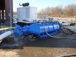
After initial conversations with the client, it was decided a trenchless method was the appropriate solution for these pipelines. However, regular CIPP was not an adequate solution. The client needed a CIPP with the thinnest possible wall thickness. It was identified that Aegion’s carbon fiber reinforced InsituMain system, with a thickness of roughly 6 mm, would be ideal for the project.
“The current market CIPP pressure liner utilizes glass fiber reinforcement to meet the required pressure rating,” Wager said. “However, the client’s requirement for a higher pressure rating that was the thinnest it could possibly be meant the utilization of carbon fiber reinforcement. Carbon fiber fabrics and materials are already used extensively in the aerospace and defense industries, as there can be some major benefits to using carbon fiber systems due to their superior physical properties. In roughly the last decade, the use of carbon fiber has begun to be used more extensively in small-diameter lining systems using CIPP. However, a CFCIPP option had never been used for this specific application.”
Due to the increased design measures used for the piping systems, the new CIPP system would need to be tested to meet National Fire Protection Assn. NFPA 24 – Standard for Installation of Private Fire Service Mains and their Appurtenances. Once this testing has been completed and the product has been completely vetted, it will be the only CIPP system approved for fire suppression lines at the client’s electric power facility and similar facilities.
Calculating Flow Capacity
To address the flow concerns for the fire suppression system, a study was done by Aaron Horbovetz, P.E., PMP, at M. E. Simpson to calculate the Hazen Williams C-Factor. Horbovetz said the Hazen Williams friction coefficient is “the industry standard for determination of pipeline carrying capacity” and “reflects the flow characteristics of the existing pipeline compared to that of a new pipe.”
Horbovetz tested an 8-in. lined pipe sample three times using identical methodology at Aegion’s R&D facility in Chesterfield, Miss. According to test documents, the system was pressurized using water from a municipal fire hydrant (ranging from 100 to 120 psi) and purged of air. Once flow stabilized, data was recorded over a 20-minute period along with the test meter flow rate. This data was then used to calculate the C-Factor. Data showed a C-Factor ranging from 155 to 160. For the specific project in mind, the C-Factor of the original host pipe was 140. Even though the installed InsituMain CIPP would result in a reduced diameter thickness of roughly 6 mm, the increased C-Factor offsets much of the inner diameter reduction to still meet the client’s flow requirements.
Additional Testing
Before getting started on product development, the team reviewed existing standards and installation guidelines for a variety of pipeline materials. The engineered solution would need to meet the minimum design requirements provided by the client.
In addition to the flow capacity, one of the main requirements concerned maintaining the operating pressure of 125 psi for the fire protection lines using stainless steel termination ends. Any initial burst pressure testing done on the line would need to have a minimum safety factor of 4, meaning that burst pressure needs to be higher than 600 psi. Additionally, because the line could potentially see temperatures as high as 150°F, the epoxy used would need to have a glass transition temperature higher than 180°F.
To meet the standards above, a robust design process was implemented to confirm that the system would provide a fully structural pressure pipe liner tested to UL/FM standards. At the time of this publication, this product is expected to be the first CFCIPP system in the industry ever certified to these standards.
To meet the first requirement for an instantaneous burst pressure of 600 psi, a carbon fiber reinforced tube was the material of choice due to its high stiffness, fatigue properties and long-term corrosion resistance. Working directly with industry partners, the custom designed triaxial carbon fiber fabric combines the benefits of circumferential 90-degree and +/-45-degree biaxial reinforcement. The carbon fiber tows (carbon fiber strands bundled together) run in perpendicular angles to add strength and reduce torsional, circumferential and longitudinal flexion and strain.
To satisfy temperature requirements, a high temperature glass transition epoxy resin was chosen. When combined with carbon reinforcement, the epoxy will provide excellent long-term retention of mechanical properties at the required elevated temperatures, making CFCIPP tube an ideal solution for the harsh operating conditions at the power facility.
To date, preliminary hydrostatic burst samples with stainless-steel ends have been tested. On average, the results show an ultimate burst pressure of 600 psi, exceeding the safety factor of 4 per the project requirements. These findings show that the CFCIPP system has the potential to be an ideal fit for the fire protection line in question.
Other Product Considerations
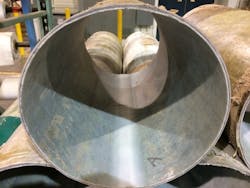
In addition to the improvements required by UL/FM, several other advancements have been made to the product and installation process. A typical CIPP tube configuration utilizes three components, including glass strengthening material, felt and a coated layer. However, for this particular system, it will be constructed using a three-layer design that incorporates a chopped strand glass mat (CSM) inner core layer, then an overlapped triaxial carbon fiber reinforcing layer and an outer polypropylene (PP) coated felt layer.
Considering the materials need to work well together during the impregnation and installation, thin layers of non-woven polyester felt were needled (sewn together) to both sides of the CSM and triaxial carbon layers. The patent-pending tube construction allowing each layer of the composite design to be bonded prior to the installation and curing of the liner is the interesting aspect of the system. This bonding enables the layers to be properly handled and vacuum impregnated with resin to ensure there is no wrinkling or bunching during the inversion installation.
Another main goal for the new system was to ensure it would work well with the current impregnation and installation processes used to create the other CIPP tubes. This will ensure the process can be repeatable on other jobs without having to buy new manufacturing equipment. The installation process is based on an industry accepted controlled head inversion process using water to cure the liner.
Installation of a CFCIPP system depends entirely on the onsite setup space and the length of each install. Since this project requires the use of stainless-steel epoxy coated spool pieces, pits will need to be dug at each end of the installation shot. There are two different installation procedures that could be used: use of a pressure inducing “torpedo” for a water inversion installation or a pull-in and expand-in-place installation.
Conclusion
Through discussions with the client and preliminary testing it has been determined that the carbon fiber-reinforced InsituMain CIPP system is a viable option for the fire suppression lines. Adding carbon to the traditional CIPP system allows the system to reach the desired flow capacity and initial burst pressures required by the NFPA and the higher of factors of safety required by these lines.
The additional testing to meet UL/FM Equivalency will allow this CFCIPP system and others like it to be approved for the trenchless repair of fire suppression lines for this client and other similar facilities.