About the author:
Glynn Nuthall is managing director for Cla-Val Pacific. Nuthall can be reached at [email protected].
Ashburton Lyndhurst Irrigation Limited, (A.L.I.L.), is situated in New Zealand’s South Island, 80 km south of the city of Christchurch, in a region known as the Canterbury Plains. It was developed in the late 1940s to provide open channel irrigation via a gravity supply canal to the local landowners.
In those days, sheep farming was the mainstay of the livestock industry, and even today New Zealand is home to more than 27 million sheep. However, in recent years dairy cattle farming has increased dramatically, and this is due to the dramatic increase in demand globally for New Zealand’s dairy products. Several large commercial milk drying plants have been built in the area to serve this fast-growing segment of the local economy.
A.L.I.L. encompasses 74,130 acres, which is the size of the Island of Singapore. The water is supplied from the Rangitata Diversion Race, an irrigation canal built between 1937 and 1944. It is 42 miles long with an average width of 49 ft , and a depth of 10 ft. It flows at 491,360 gallons per minute (gpm), with the schemes allowance being 206,054 gpm.
During 2007, approval was given for a $5.1 million USD, project to install a pipeline in a part of the scheme comprising the installation of 19 miles, of pipe, supplying 37 farms and irrigating 9,884 acres.
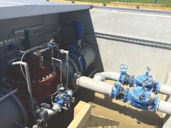
A single 40-inch mainline was installed, which included Cla-Val 90 series pressure reducing valves (PRV) to control the pressure as the pipeline descended down the plains. Two 24-in. and two 16-in. valves along with associated bypass and relief valves were installed. Along with these were 37 farm supply valves, 90 series valves ranging in sizes from 3 in. to 10 in.
In 2013 after seven years of continuous duty, the first valve was taken out of service for inspection. These were a 16-in. pressure reducing valve and a 6-in. pressure reducing bypass valve. Both valves were in excellent condition and were returned to service using the original parts, and the decision was made to do another inspection at the 10-year mark.
At the 10-year mark in 2016, an inspection was performed on a 24-in. valve and an 8-in. bypass valve and again the valves were found to be in excellent condition and were returned into service, resulting in a decision to inspect the valves again in 2021.
Since the initial piping scheme, the decision has been reached to install an additional 124 miles of pipeline, serving an additional 167 properties at a cost of $60.7 million USD. This also includes Cla-Val control valves for each property ranging is sizes of 1.5-in. to 14-in. plus main line electronic control valves in sizes of 14, 24, 36 and 40 in., along with bypass and relief valves.
Following the success of this scheme, Cla-Val supplied neighboring irrigators, namely Barrhill Chertsey Irrigation Limited, with automatic control valves. Barrhill Chertsey received 45 valves in sizes 4 inches to 12 in. CPWL Stage 1 used 219 valves, including four 24-in., five 30-inch electronic control valves. CPWL Stage 2 required 222 control valves including three 36-inch electronic control valves with 14-inch bypass valves.
The mainline pressure control valves in sizes 14, 24, 36 and 40 in. are Cla-Val Model 131 Series electronic control valves with Cla-Val VC22D controllers and were installed with X143 Turbine Generators.
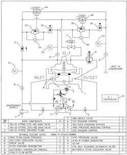
Above is the valve schematic and operation of one of the 40-in. control valves with 6-in. bypass valve.
Valve Operation
On low flow, the 6-in bypass PRV, equipped with a hydraulic pilot, controls downstream pressure. As demand increases, and the bypass PRV opens above 80% for more than 60 seconds, the 40-in electronically controlled main PRV then will start to open, allowing flow to transition to the bigger valve. The bypass PRV is then forced and held closed while the main PRV regulates the downstream pressure. When the demand decreases and the main PRV is open less than 8%, the bypass PRV will then be released and allowed to open, allowing flow to transition back to the smaller valve. The main PRV is then forced and held close, while the bypass PRV regulates the downstream pressure.
A secondary hydraulic pilot system acts as a back-up in case of power failure. The hydraulic circuit is kept isolated by two 2-in. hytrol valves held closed by an energized solenoid wired to an external relay and powered independently. The hydraulic pilot set point is the same as that of the electronic set point.
In the event of a power outage, the solenoid is de-energized and would change state, allowing the two hytrol valves to open. When open, the secondary hydraulic pilot system on the main PRV would run and regulate the downstream pressure with the smaller bypass PRV acting as such.

