Six-mile effluent pipe remediates algae blooms in Great Salt Lake
In addition to decades of water loss, the shrinking Great Salt Lake (GSL) faced another grave situation: algae.
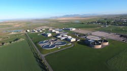
The build-up of algae in the lake’s Farmington Bay area was nurtured by wastewater from the nearby treatment plant, which was no longer able to sufficiently mix it with the saltier water of the lake. Instead of continuing to use that bay as the outfall, the North Davis Sewer District (NDSD) elected to construct a 6-mile, 63-inch diameter pipeline to redirect effluent to the lake’s Gilbert Bay where the algae could not grow while still meeting the water needs of the GSL.
The solution itself, however, faced its own set of obstacles. The new pipeline would need to provide a high flow capacity, be able to be buried in unstable soils, withstand the corrosive, high salt content of the lake and soil, fight seismic shifts and liquefaction, and provide a cost-savings solution as well.
Weighing the options
Mitch Dabling, P.E., now with HDR Inc., said the state wanted options to reduce nutrient loading into the lake. To do so, it looked to wastewater plants like those in the North Davis Sewer District’s system.
“We started brainstorming different ideas, one of which was to replace the entire plant, which would’ve been about $500 to $600 million,” Dabling said. “Our recommendation, with a $55 million dollar budget, was rather than replacing it, to build a pump station and a pipeline that takes that treated effluent water out into the main body of the Great Salt Lake.”
In doing so, Dabling noted the first big benefit from such a move would be a reduction in algae bloom issues, which can be exacerbated by nutrient loading. The second benefit he recognized was that more water would enter the Great Salt Lake, which has struggled due to high temperatures and drought.
“Right now, the Great Salt Lake is a really hot topic with its low lake levels. It’s been drying up during the last 20 years,” Dabling said. “And where we were originally discharging, the water would fan out and evaporate before it even got to the lake itself. The new pipeline would be able to take that water, pump it in a high-density polyethylene (HDPE) pipeline all the way out into that main body where there’s salt, destroying algae growth, and put more water into the lake. Everyone agreed that it was a great solution.”
The Great Salt Lake has three areas: Farmington Bay, between the north and south causeways of Antelope Island; Gilbert Bay, which is north of Antelope Island; and Gunnison Bay, the north arm of the lake.
NDSD collects and treats wastewater from the cities of Clearfield, Clinton, Layton, Roy, Sunset, Syracuse, West Point, and Kaysville. Each city owns and operates its own system of sewage collection lines that serve many subdivisions and discharge into the larger district-owned lines.
The NDSD collection system consists of nearly 100 miles of sewer lines ranging from 8 to 84 inches in diameter. The majority are reinforced concrete pipe with the oldest dating back to the mid-1940s. NDSD facilities treat up to 34 million gallons a day (MGD) that previously would be discharged into Farmington Bay.
The pipeline plan
During 2018, NDSD began investigating methods to meet stricter nutrient load requirements implemented by the State of Utah. By working with the state, NDSD was able to invest in a capital improvement project consisting of a pump station and pipeline instead of a new treatment facility that would have been required to meet the state’s recently implemented Technology-based Phosphorus Effluent Limits (TBPELs).
This requires a minimum level of treatment of pollutants for point source discharges based on available treatment technologies, while allowing the discharger to use any available control technique to meet the limits. The approach resulted in treated effluent remaining in the GSL, helping to keep water in the lake, which frequently experiences historically low water levels. NDSD’s evaluation included the long-term health of the GSL, the water level of the lake, meeting the discharge requirements of Farmington Bay, limiting the growth of invasive phragmites, and maintaining wildlife habitat.
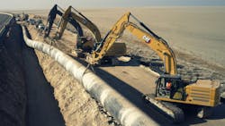
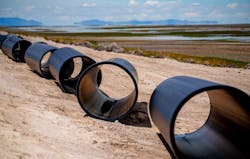
The new pipeline plan called for using 63-inch diameter DR 26 PE 4710 HDPE pipe as a monolithic line with leak-free joints all along its 33,000 feet. It would be installed in the shoulder of a two-lane road built on the Antelope Causeway connecting Antelope Island to the mainland.
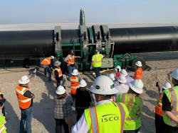
Coming as 40- and 50-foot sections from the Pipeline Plastics plant in Levelland, Texas, they were heat fused on site using a McElroy MegaMc 2065 fusion machine. ISCO Industries, a global HDPE piping solutions stocking provider, coordinated delivery of the pipe with Pipeline Plastics and handled the complex fabrications at its Kingman, Arizona, facility before transporting the completed pieces to Utah. Whitaker Construction Company assembled and installed the pipe.
The undertaking was named Project of the Year for the Municipal and Industrial Division of the Plastics Pipe Institute, Inc. (PPI), the major North American trade association representing the plastic pipe industry. Each year the PPI membership reviews and votes on Project of the Year and a Member of the Year for each of the five PPI divisions. The award was presented to PPI member company Pipeline Plastics during the group’s worldwide membership meeting held in May 2023.
“This project redirected badly needed water back into the Great Salt Lake to meet state nutrient level requirements and protected ecosystems,” said David M. Fink, PPI president, during the award ceremony.
Fink explained HDPE pipe was chosen due to the high chloride content of the corrosive soil, which was a significant concern for the project in addition to the high salinity of the GSL. The corrosion resistance of plastic pipe was a primary factor in its selection for the project, he added. Dabling reiterated that statement.
“The first thing we did was identify the need to go to a plastic pipe of some sort because of corrosion concerns,” Dabling said. “The Great Salt Lake is eight times saltier than the Pacific Ocean and anything metal will rust and corrode very, very quickly. From a longevity standpoint, it really made sense to go to a plastic pipe material. The biggest benefit for HDPE was this is also a seismically sensitive area, and it’s in a liquefaction zone.”
The causeway is built on a lake bed, and Dabling explained that 60 years ago, granular engineered fill was poured on top of that lake bed to create a drivable surface. During a liquefaction event, the road will spread laterally by so significant a margin that the geotechnical analysis identified it as a major concern.
“We did evaluate and consider other types of pipe such as welded steel and ductile iron, but the corrosion protection systems that would be required would have been extremely expensive and, probably very ineffective,” Dabling added. “We also evaluated a jointed material like C900 PVC pressure pipe but our biggest concern there was that in a lateral spread event, we’d probably have joint failures where it would pop out. And so, HDPE being butt fused gave us more confidence that it would be able to withstand or have less damage during a seismic event.”
Camille George Rubeiz, P.E., F. ASCE, co-chair, HDPE Municipal Advisory Board, and senior director of engineering for the PPI Municipal & Industrial Division said the chosen pipe — HDPE 4710 — meets AWWA C906 and ASTM F714 standards while also fulfilling the projects other targeted needs.
“It is the highest performance classification of HDPE piping material for water applications, and ideally suited for areas just like the Great Salt Lake,” Rubeiz said. “One of the newest technical documents from our Municipal Advisory Board, MAB-9, provides the basis for determining the proper wall thickness for a fused, highly ductile, flexible HDPE water pipeline in a seismically sensitive area when subjected to an induced lateral spread.”
MAB serves as an independent, non-commercial adviser to the Municipal & Industrial Division of PPI. MAB-9, Design of HDPE Water Mains for the Lateral Spread Seismic Hazard, is available on the PPI/MAB’s website.
Logistics optimizations cut down on greenhouse gas emissions
According to PPI, there was another benefit — the reduction of CO2 emissions. This was due to Pipeline Plastics ability to make the 63-inch diameter pipe in 40- and 50-foot sections instead of the traditional 20-foot lengths of many other types of pipes.
“If we made and supplied the pipe in the typical 20-foot lengths,” explained Stephen Boros, vice president of engineering Pipeline Plastics, “that would have meant only 40 feet of pipe could have been transported on each truck, resulting in around 825 truckloads. According to the EPA and commercial studies, a fully loaded flatbed truck (44,000 lbs.) emits 0.46 kg CO2 per mile. Having sticks that were about twice as long saved 460 truck trips, or more than 400,000 truck miles, eliminating more than 180 metric tons of CO2 emissions, which greatly enhanced the ESG aspects of this project.”
Flow, pressure & hydraulics considerations
To design the system hydraulics, three flow conditions were analyzed: 28, 34, and 60 million gallons per day.
“We decided to oversize the pipe because of the difficulty in constructing additional capacity in the effluent pipeline alignment as discharges increase over time with future growth in the service area,” Dabling said.
The DR 26 pipe with a wall thickness of nearly 2.5 inches was selected to provide sufficient structural stability due to the poor soils associated with the GSL lake bed. The pipe has a working pressure rating of 80 psi, significantly larger than the system requirement of 50 psi, with an additional 80 psi surge pressure capacity. Water from the treatment plant goes into an energy dissipation structure at the end of the pipe with an overflow weir, which enables the pipeline to maintain its pressure.
Whitaker Construction evaluated the fusion process of the large pipeline, and ultimately concluded segments were to be connected using thermal butt-fusion welds.
Whitaker was required to remove two joints within the first 1,000 feet of pipeline, and two joints every 5,000 feet thereafter. These joints were visually inspected as well as destructively tested with a guided side bend test ASTM F3183.
“It was a really good QC process that we enforced, and they (Whitaker) did a great job,” Dabling said.
About the Author
Steve Cooper
Steve Cooper is a writer for SCA Communications. Cooper can be reached at [email protected].


