Saving Energy in Water Reuse Applications
About the author:
John V. Ballun, P.E. is president and CEO of Val-Matic Valve & Mfg. Corp. Ballun can be reached at [email protected].
Given the scarcity of freshwater in drought-stricken areas, advances in water reuse projects are an essential element of the solution. Equipping a wastewater plant with a non-potable or reclaimed water reuse system reduces water demand, provides revenue for the water utility and reduces the costs of the outfall system.
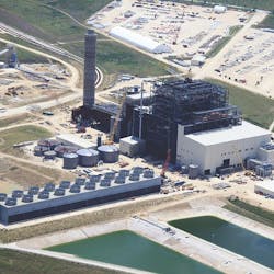
The 900 mWh Sandy Creek Energy Station in Riesel, Texas, deploys efficient and reliable technology for coal-fueled plants utilizing supercritical steam generators and advanced technology solutions that are designed for sustainability through enhanced efficiency and environmentally friendly systems, processes and components for greater efficiency and lower emissions. Moreover, the energy station’s cooling water is sourced as reclaimed water from the Waco Metropolitan Area Regional Sewerage System (WMARSS) wastewater treatment plant located two miles away in Waco, Texas.
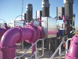
Not only does the community of Waco benefit from providing reclaimed water to the power plant, but advanced valve systems were used to safely and efficiently deliver the reclaimed water to the energy station. The treated effluent flows by gravity to a below ground wet well for storage and pumping where three 16-in. high service pumps deliver the reclaimed water through a 36-in. pipeline to the energy station. Every pump requires a check valve to prevent reverse flow, but instead of the traditional swing check valve, ball valves built in accordance with American Water Works Assn. (AWWA) standard C507 were installed, see Figure 2.
Energy Calculations
Ball valves are used for pump discharge applications because they provide significant energy savings. Pumps consume energy to overcome the static head and friction losses. Headloss can be converted into energy cost related to the electricity needed by the pump to overcome the additional headloss from the valve using the equation in the information box on to the right.
The energy consumption difference between two valve selections can be calculated by using the headloss difference between the two valves for the variable ∆H in the equation in the box below. For example, the difference in headloss between a 16-in. ball valve and 16-in. swing check valve operating at 10 ft per sec (6267 gpm) is approximately 2.5 ft of head. Therefore, assuming the pumps run 50% of the time with an efficiency of 80% and an electrical cost of $0.08 per kW-hr for 40 years, the 40-year cost can be estimated by pluggin those figures in. See the example below:
• Total Cost = 40 (1.65 x 6267 x 2.50 x 1.0 x 0.08 x 0.5) / (0.8)
• Total Cost = $51,700 over 40 years per valve
The calculation shows that the use of a 16-in. AWWA ball valve in the place of a swing check valve can save $51,700 per valve over the life of the plant. It is clear that valve selection can play an important role in energy savings. Moreover, saving electrical energy also reduces the need for burning fossil fuels and creating greenhouse gases (GHGs). On a national average, for every kW-hr of electricity used, about 1.14 lb of CO2 emissions are generated. In the example mentioned above, the use of a ball valve instead of a swing check valve would result in savings of 368 tons of CO2 emissions per valve over the 40-year life of the system.
AWWA ball valves also can precisely control changes in flow rate to prevent check valve slam and surges in water pipelines. Since ball valves are slow-closing quarter-turn valves, they are not subject to check valve slam. Further, when pipelines are several miles long, it is important for pump control valves to operate slowly, over several minutes. This slow operation protects the pipeline from rapid changes in fluid velocity when the pumps are started.
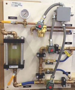
On long pipelines, every 1 ft per second of velocity change can create a 50 psig surge on top of the system pressure. Starting just one of the three pumps could boost the velocity in the 36-in. pipeline several feet per second potentially causing a 200 psig surge. The solution is to control the opening and closing of the pump control ball valves slowly over 60 to 300 seconds using an air-oil control panel powered by a routine 80 psig air supply, as shown in Figure 3.
While an air supply system is standard equipment, it is difficult to operate large quarter-turn valves slowly and smoothly with air because air is compressible and does not rigidly secure the actuator cylinder during motion. The solution employed here was to use compressed air as the supply media and an air/oil control system. Hydraulic oil also provides great lubricity and is not compressible, so the valve control is smooth and precise.
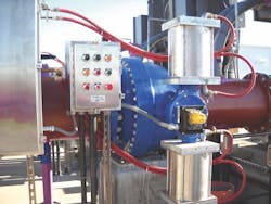
The ball valve is operated by a dual-cylinder actuator with stainless steel opposed cylinders, see Figure 4. The top cylinder is powered with 80 psig air pressure through the 4-way solenoid valve and drives the valve open and closed. The bottom cylinder is filled with hydraulic oil, which is piped to the hydraulic control panel. In the hydraulic panel, two-way solenoid valves are included to provide rapid oil flow to close the ball valve rapidly on power failure. The normal opening and closing speeds of operation are controlled by two independent flow control valves to prevent surges and water hammer in the pumping system. A make-up oil tank is needed to compensate for the difference in oil volume of the rod end and cap end of the oil cylinder.
The ball valve sequence of operation is similar to any check valve but with a twist. When a pump is started, the discharge pressure is sensed by a pressure switch, which in turn, sends electrical power to the four-way solenoid valve, opening the ball valve. The twist comes in the “stop” mode. When the “stop” signal is given, the four-way is de-energized, closing the ball valve, but the twist is that while the ball valve is closing, the pump continues to run. The pump continues to run until the ball valve is fully closed and then a limit switch on the valve trips off the pump. In general, the ball valve operates like a check valve, but it does so in slow motion and with no slam.
An electrical panel acts as an interface between the valve and the main pump control panel. It displays pump operation, valve position and provides local control of the valve. Upon receipt of a pump “start” signal, the pump discharge is monitored by an adjustable pressure switch mounted on the discharge of the pipe. If the pump does not reach normal operating pressure of 110 psig within an adjustable time period of one to 10 minutes, a safety circuit will close the ball valve, provide an “emergency stop” signal and lock out the system until a reset button is pressed. The panel is wired to the pump control drive for remote monitoring of conditions and helps protect the pumping system from abnormal operating conditions.
Conclusion
Technological advances related to pump control valves provide a significant contribution to pumping system performance and energy savings. The AWWA ball valve provides low headloss and equal percentage flow characteristics to eliminate check valve slam and prevent system pressure surges. Ball valve hydraulic and electric control panels provide reliable operation, field adjustability and smart monitoring of
system operation.


